Rendering
A set of tutorials to create molecular surface, get realistic and artistic visual effects, render a scene like a cartoon…
-
How to get a sphere representation?
-
How to create a surface appearance?
-
How to get more realism with ambient occlusion?
-
How to get a cartoon effect?
-
Various effects
-
How to modify the opacity of a DNA model?
How to get a sphere representation?
Here is shown the steps to represent atoms as spheres
1/ Load a PDB file (1KX5 in the example below). The default reprensation is point cloud:

2/ Go to the Light tab in the right panel, choose Molecule instead of Plain. Choose the point size (2 in the example below):
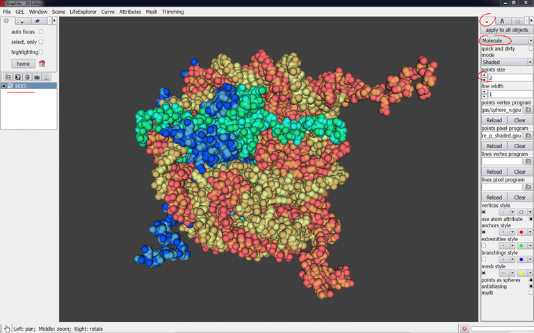
Notice: Each chain is colored differently. However the color set is very restricted and different chains can be colored identically like in the example above (PDB 1KX5 made of 10 chains A to J).
How to create a surface appearance?
This tutorial shows how to create a surface, adjust its precision, color this surface and highlight regions of the surface in different colors.
(by D. Larivière, Fourmentin-Guilbert Foundation and S. Hornus, INRIA-LORIA)

PDB file needed: 2AOQ
0/ Edit the text file 2AOQ to remove heteroatoms. They do not pose any problem but they will add “side effects” when coloring specific regions of the surface in different colors.
1/ Launch Graphite-LifeExplorer
2/ From the Graphite-LifeExplorer window click on Load PDB:
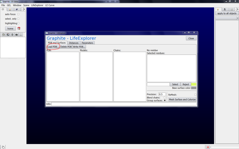
3/ Find 2AOQ.pdb in your hard disk and click on Open:

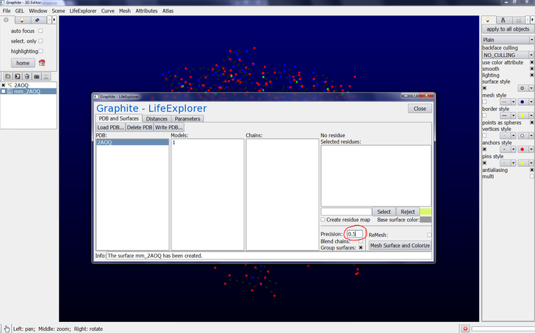
4/ Click on Models from the Graphite-LifeExplorer window: You notice that 2AOQ is made of 1 model and 3 chains A, B, C. It means that you can create a surface for the whole structure or selectively for a specific model or a specific chain:

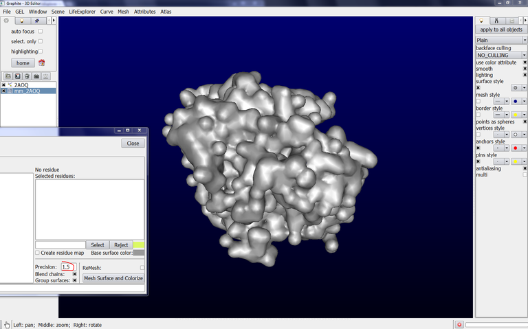
5/ Click on AOQ from the Graphite-LifeExplorer window and click on Mesh Surface and Colorize. You obtain a surface like in the image below:


6/ You can adjust the precision of the surface (we do not propose the correspondance between the “precision” parameter and the resolution of the surface yet) by modifying the number in Precision:
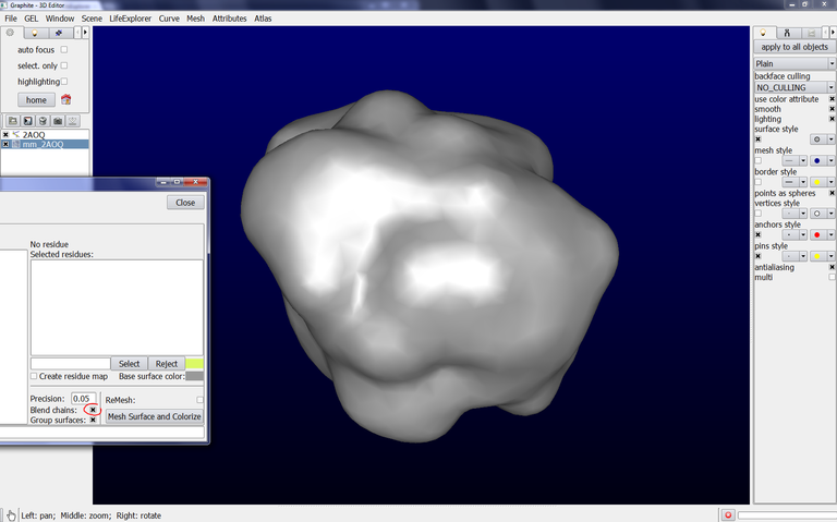
Precision = 0.05 generates this appearance:

7/ The surface above clearly displays the separation between chains. You can get a homogeneous appearance by clicking on “Blend chains” before “Mesh Surface and Colorize”:
8/ To get a surface showing a better precision, set “Parameter” to 1.5, click on Remesh and then on “Mesh Surface and Colorize”. The surface appearance looks like this, very close to the molecular surface:
Coloring the surface:
9/ To modify the surface color, click on Base surface color and choose a color. Then, simply click on Mesh surface and Colorize and the color change is effective instantly:


Coloring specific regions on the surface:
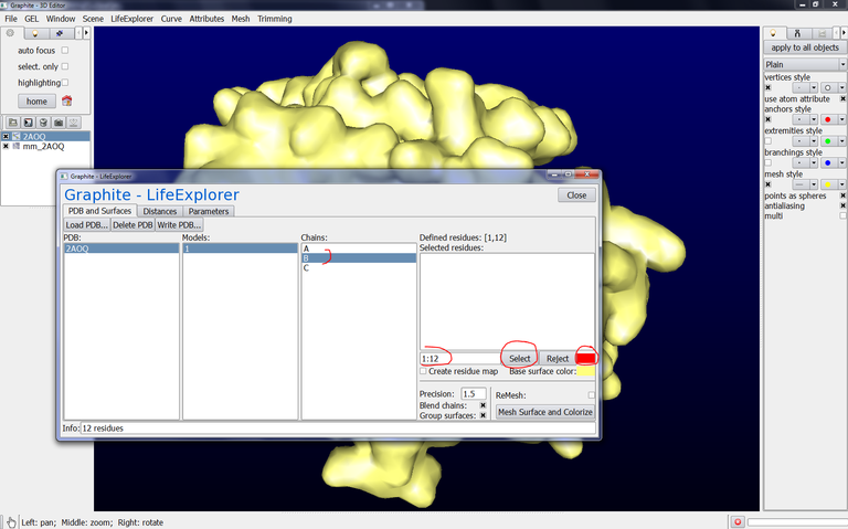
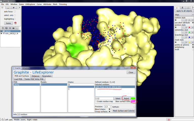
10/ From the Graphite-LifeExplorer window, click on Model 1 and then on chain B, type 1:12 in the text box like in the image below, select the color, press Select. Do the same with Chain C:

11/ Click on 2AOQ as shown in the image below and then on Mesh Surface and Colorize. The surfaces of the DNA strands are colored in blue, in red while the surface of the protein is in yellow:

12/ Go back to the Graphite-LifeExplorer window. Select chain A. Type 50, in the text box, choose a color, type 80, choose a color and click on on Mesh Surface and Colorize:


Note that the residue 50 is displayed but not 80 which is not located at the surface.
You could also type 50,80 in the text box but a single color can be chosen.
Coloring chains in different colors:
13/ Go to the outliner, select the object corresponding to the surface and suppress it. The surface is suppressed in the 3D view:

14/ Go back to the Graphite-LifeExplorer window. Select chain A and click on Mesh Surface and Colorize. Only the surface corresponding to the chain A (with the residues 50 and 80 highlighted in another color) is created:
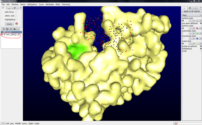
Note that this surface is named mm_2AOQ.1.A (mm = molecular mesh, 2AOQ = PDB code, 1 = model id., A = chain name). You can rename this object (select it in the outliner and go to the Scene menu, select Rename Current).
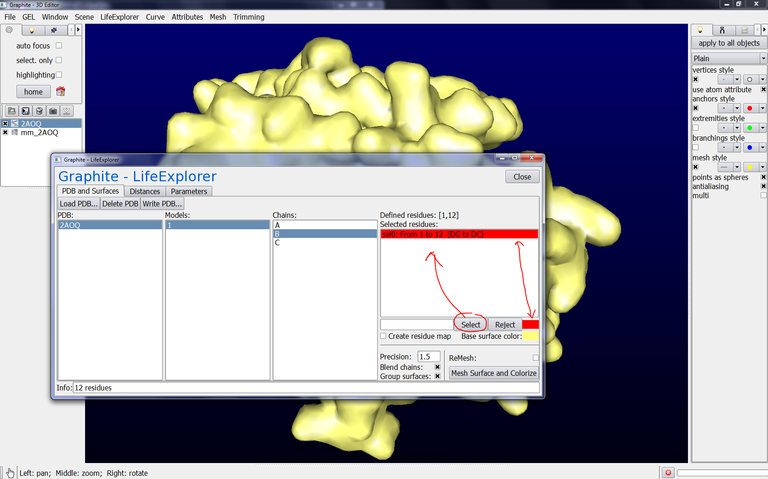
15/ Go back to the Graphite-LifeExplorer window. Select chain B, click on sel0: From 1 to 12 (DG to DC), click on Reject, change the color and click on Mesh Surface and Colorize. The surface of chain B is displayed and this surface correspond to an object named mm_2AOQ.1.B in the outliner:

One benefit in having all chains as separated objects in the outliner is to display the surfaces in different colors.
However, you can also obtain this result this way:
Select 2AOQ in the Graphite-LifeExplorer window. Delete PDB. Load PDB and choose 2AOQ.
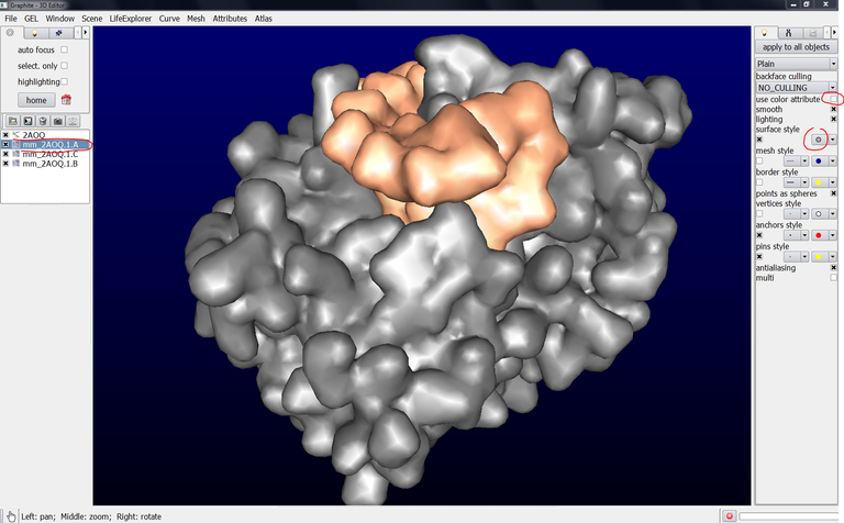
Click on 2AOQ and unckeck “Group surfaces”. You obtain effectively 3 objects in the outliner corresponding to the 3 chains but only one color like in the image below. However,…

… however, you can change the color of each chain, let’s say chain A, by selecting mm_2AOQ1.A in the outliner, unchecking “use color attribute”, the color of chain A is no more the color chosen from the Graphite-LifeExplorer window but a default grey color:
The color of chain A can be modified by clicking on the surface style color panel and choosing a color:

Better smoothing of the surface:
Let’s suppose that seeing the triangle forming the surface is not acceptable:

Select mm_2AOQ.1.A in the outliner, go to the Mesh menu, select Global, then split and choose Split_cloop in the rolling menu and press OK. Do the same for chain B and C. The surface appears smoother :

How to get more realism with ambient occlusion?
Ambient occlusion attempts to approximate the way light radiates in real life. In Graphite-LifeExplorer, it can be used in real-time and not solely at the final rendering stage (by D. Larivière, Fourmentin-Guilbert Foundation and S. Hornus, INRIA-LORIA)
Graphite-LifeExplorer release version: 05 04 2012
File needed: Ftsk.gsg
Recommended tutorial: How to create a surface appearance? in the Rendering section.
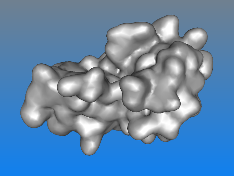
This tutorial shows the steps to get this kind of rendering below. Such a rendering is helpful to better sense the depth:

1/ Launch Graphite-LifeExplorer
2/ From the File menu load Ftsk.gsg (Note : gsg = Graphite Scene Graph). The 3D view looks like as follows:

3/ Move the camera to get this view:
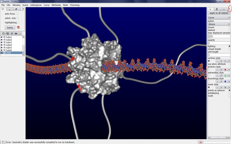
4/ Click on the arrow shown in the image above up to the FX tab to be displayed and click on it:

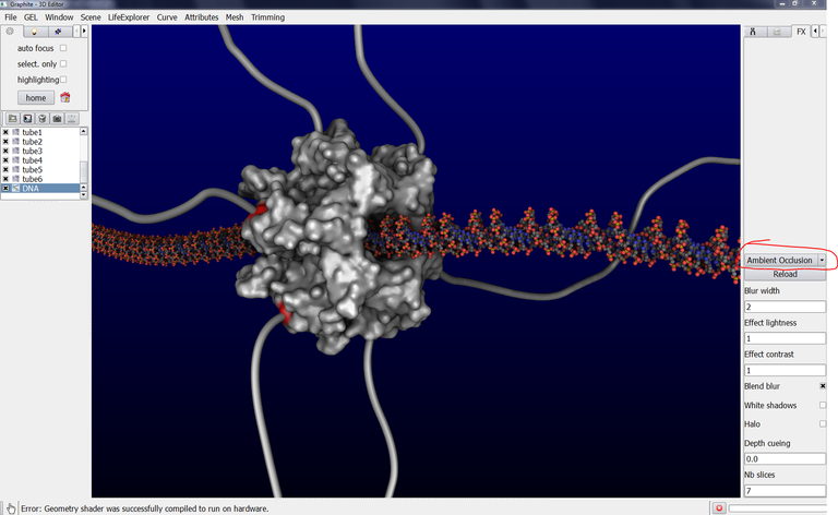
5/ Click on the “None” rolling menu and select Ambient occlusion. The rendering in the scene is slightly modified:
6/ Select DNA in the outliner, go to the “Lighting” tab, and uncheck “Lighting”. The rendering of the DNA is modified:

7/ Go to the “Lighting” in the left upper side of the user interface and select the colors as shown in the image below:

8/ Select mm_2IUU in the outliner, go to the “Lighting” tab, and uncheck “Lighting”. The surfacic rendering of the protein FtsK is modified:

9/ Select tube1 in the outliner, go to the “Lighting” tab, and uncheck “Lighting”. The surfacic rendering of the tube (linker 1) is modified:
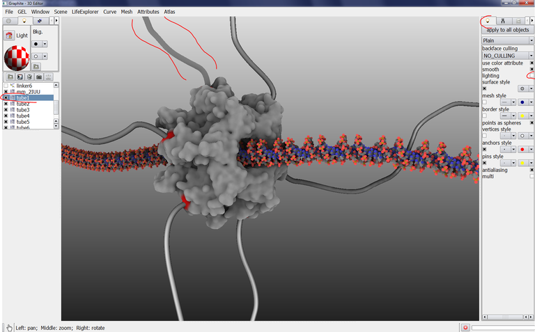
10/ Do the same for tube2 to 6:

11/ Go back to the FX tab. Change the parameters this way: Blur width = 2, Effect lightness = 0.9, Effect contrast = 1.9, check Blend blur, uncheck White shadows and Halo, Depth cueing = 0.2, Nb slices = 7:

Note that this rendering is real-time! You can explore and set the parameters up to get a rendering you particularly like.
How to get a cartoon effect?
This tutorial shows how to get a cartoon effect
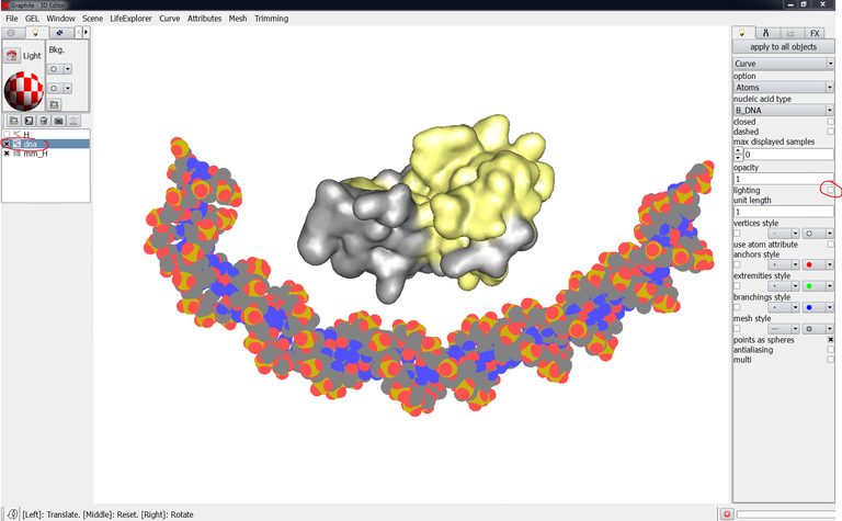
1/ Import a protein in the scene and give it a surface appearance with two colors (see this tutorial before). Then create a DNA molecule (as shown here). The scene looks like in the image below:

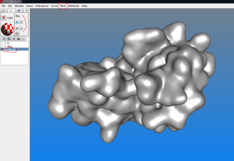
2/ Turn the grey (or blue if it is the default color) background to white as indicated in the image below:

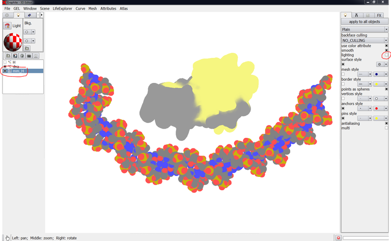
3/ Select “DNA” in the outliner and uncheck “lighting” in the “light” tab:
4/ Select the protein surface in the outliner and uncheck “lighting” in the “light” tab:
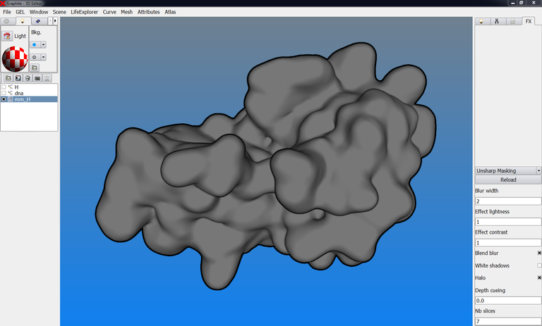
5/ Go to the FX tab, and select “Unsharp Masking” instead of “None”: details appear at the surface of the objects while they remain flat:
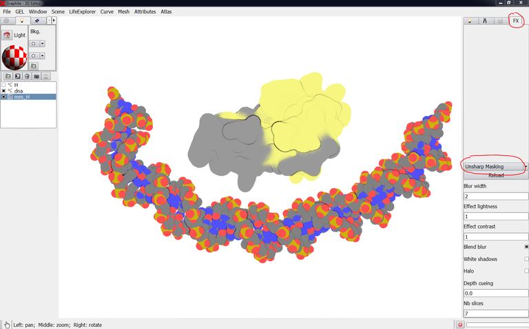
6/ You can reinforce the contour by checking “Halo”:

You can try various combinations of parameters (Blur width, Effect lightness,…) and look at the effects.
Various effects
Here we show rendering effects as we find them during our modeling works
One major effect, ambient occlusion, is already described here as well as the cartoon effect.
1/ Load a PDB file corresponding to a protein. Give it a surface appearance. Here the background is displayed in a dual color (light blue and light grey):
2/ Select the surface in the outliner, go to Mesh, Global, Split and choose C_loop:
3/ Go to the “Light” tab, select “Textured” instead of “Plain”, and “checkerboard” in Mode:

4/ Go to the FX tab, select “Unsharp Masking” and check “Halo”:
How to modify the opacity of a DNA model?
Here we show how to see control points through a DNA duplex displayed as an atomic representation
The scene below contains a DNA duplex created with the cubic Bezier tool. We wish to modify the shape of the DNA but the atomic current representation does not allow to see the control points forming the DNA curve/helix:
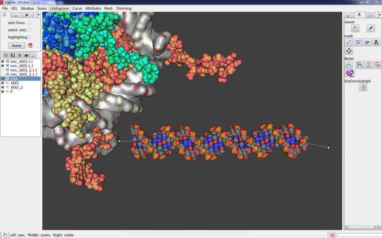
1/ Select DNA in the outliner. Go to the Light tab in the right panel, type 0.4 in opacity: you can now see through the DNA and locate the control points:

Note that a bad and unexpected behavior is observed when ambient occlusion.